| Home |
Durable 50 GHz to 75 GHz Insertion loss 1.25 db max. Return loss 15 db max. Individually spring loaded contacts Measurement repeatability -50 db Bias T option available Patented coaxial design
| FIGURE 1 |
The MODEL 75 PICOPROBE® sets new standards in microwave probing performance. Benefiting from coaxial techniques, which have inherent low loss and low dispersion characteristics, the Model 75 Picoprobe, with or without the bias T option, achieves an insertion loss of less than 1.0 db (typical) and a return loss of greater than 15 db (max.) over its frequency range.
With its individually spring loaded, Beryllium-Copper tips, the Model 75 Picoprobe® provides reliable contacts, even when probing non-planar structures. This reliable low resistance contact is one of the keys to providing highly repeatable measurements (-50 db) at V band frequencies. The Model 75 Picoprobe also provides direct viewing of the probe tips for accurate positioning.
Any pitch (tip spacing) from 50 microns and up may be specified. The probe can be configured with Ground-Signal-Ground (G,S,G), Ground-Signal (G,S), or Signal-Ground (S,G) tip footprints. We recommend smaller pitches with a G,S,G footprint for best performance. Most customers are using GSG probes with a pitch of 100 to 250 microns.
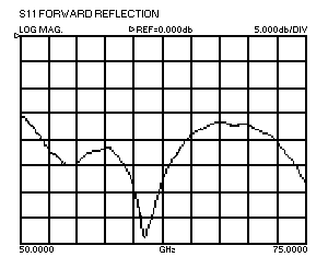 |
Left:Typical uncalibrated performance of a Model 75-GSG-100-BT while touching a 50 Ohm load on our CS-5 Calibration Substrate. |
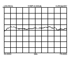 |
Left:Typical insertion loss of a Model 75-GSG-100-BT. |
 |
Left:The Model 75 Picoprobe's Bias T provides a direct low resistance DC path for supplying up to 1.5 A to a device under test. The Bias T has special circuits which add loss at frequencies below the cut-off frequency (39.86 GHz) of WR-15 waveguide. This data was taken by launching a 40 MHz to 67 GHz signal from the tips of a calibrated Model 67A into the tips of a Model 75-GSG-150-BT. Without this low frequency loss, most active devices will oscillate. |
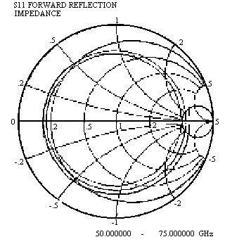 |
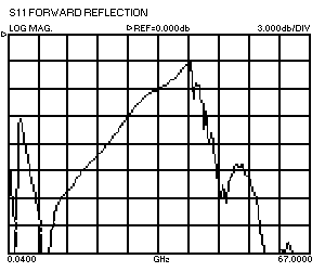
Left:Forward reflection of a Model 75 into an open ended 50 ps coplanar line after a one port SOLT calibration was performed using our CS-5 Calibration Substrate. The smooth inwardly spiraling line shows the increasing loss of the 50 ps coplanar line with frequency, coupled with a smoothly changing phase. The CS-5 Calibration Substrate will also perform excellent LRL/TRL and LRM/TRM V-band calibrations. More data is available on request. |
| FIGURE 2 |
|
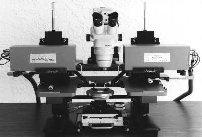
Micropositioners are available to hold Wiltron V band modules
so that the module and the probe are micropositioned as a unit.
In this way, total ease of positioning can be achieved with minimum
insertion loss. |
 |
|
 |
|
|---|---|
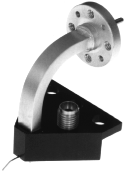
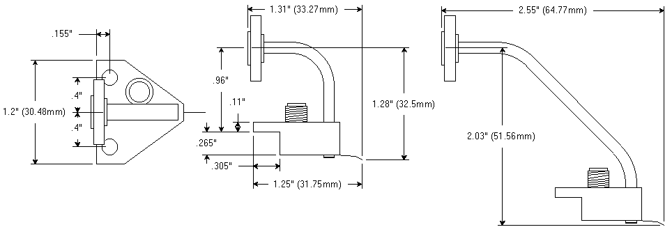
| Model 75-BT Waveguide Dimensions |
Model 75-BT-M Waveguide Dimensions |
| FIGURE 4 |
|
| Home Page |
| GGB INDUSTRIES, INC. | P.O. BOX 10958 | NAPLES, FL 34101 USA |
| Telephone (239) 643-4400 | Fax (239) 643-4403 | Email email@ggb.com |