| Home |
The MODEL 50 PICOPROBE® sets new standards in microwave probing performance. Benefiting from coaxial techniques, which have inherent low loss and low dispersion characteristics, the Model 50 Picoprobe®, with or without the bias T option, achieves an insertion loss of less than 0.8 db (typical) and a return loss of greater than 15 db (max.) over its frequency range.Durable 33 GHz to 50 GHz
Insertion loss 1.0 db max
Return loss 15 db max
Individually spring loaded contacts
Measurement repeatability -55 db
Bias T option available
Patented coaxial design
FIGURE 1
| Picoprobe® Model 50 Data | |
|---|---|
Typical uncalibrated performance of a Model 50-GSG-100-BT while touching a 50 ohm load on our CS-5 calibration substrate |
 |
Typical insertion loss of a Model 50-GSG-100-BT |
 |
| The Model 50 Picoprobe® bias T provides a direct low resistance DC path for supplying up to 1.5 A to a device under test. The bias T also has special circuits which add loss at frequencies below the cut off frequency (26.34 GHz) of WR-22 waveguide. This data was taken by launching a, 40 MHz to 50 GHz, signal from the tips of a calibrated Model 67A into the tips of a Model 50-GSG-150-BT. Without this low frequency loss, most active devices will oscillate. |  |
| FIGURE 2 |
|
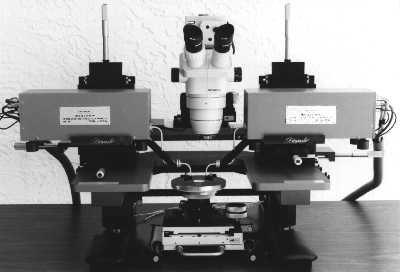
Micropositioners are available to hold Wiltron V band modules
so that the module and the probe are micropositioned as a unit.
In this way, total ease of positioning can be achieved with minimum
insertion loss. |
 |
|
|
| Home Page |
| GGB INDUSTRIES, INC. | P.O. BOX 10958 | NAPLES, FL. 34101 |
| Telephone (239) 643-4400 | Fax (239) 643-4403 | Email email@ggb.com |