
| Home |
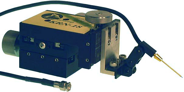
PICOPROBE® MODEL 10 is a multipurpose, high speed, passive probe which can be used for driving as well as receiving signals. The Model 10 consists of a one meter length of flexible 50 ohm coaxial cable terminated by a carefully trimmed SMA on one end and by a miniature, high speed 50 ohm connector, specially developed to receive Model 10 replaceable coaxial probe tips, on the other. The 50 ohm coaxial cable was custom designed for Model 10 to be high speed, yet very flexible, so that moving the cable would not disturb the probe points.
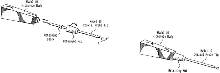
Adaptable for a wide range of applications, the Model 10 uses a variety of special purpose, easily replaceable probe tips. Each probe tip consists of a 1.5 inch long 50 ohm semi-rigid coaxial line, a retaining nut, one or two probe points, and a variety of electrical components tailored to achieve the desired electrical characteristics. To drive or receive signals on 50 ohm circuit points, the Model 10 should be fitted with a probe tip that has two probe points, one for the ground and one for the signal. Probe points which extend 0.120 inches beyond the 50ohm coaxial probe tip have been designed for dc to 3.5 GHz response and probe points which extend 0.030 inches beyond the probe tip have been designed for dc to 7 GHz response. The longer 0.120 inch tips are more flexible, making them more durable and easier to use than the shorter 0.030 inch style.
To receive signals from high impedance circuit points, Model 10 probe tips with a 250 ohm, 500 ohm, or 5 k ohm input resistance should be used. All have been trimmed to compensate for cable loss and to minimize the need for a short ground. Grounding methods would depend upon the desired frequency response and range from dual probe points to a 6 inch long flexible ground strap. In applications where many circuit points must be accessed and ground is not conveniently located, a flexible ground strap can be substituted for the ground point.
The 250 ohm tip should be used with 0.180 inch long dual probe points to achieve dc to 10 GHz response. The signal will be attenuated by 5:1. The 500 ohm tip should be used either with 0.180 inch long dual probe points to achieve dc to 11 GHz response or with a 2 inch long ground strap to achieve dc to 4 GHz response. The signal will be attenuated by 10:1.
The 5k ohm tip should be used either with 0.180 inch long dual probe points to achieve dc to 5 GHz response, a 2 inch ground strap to achieve dc to 4 GHz response, or a 6 inch ground strap to achieve dc to 2 GHz response. The signal will be attenuated by 100:1.
To drive high impedance circuit points Model 10 probe tips with a 50 ohm terminating resistor should be used.
Model 10 was designed to be attached to any micropositioner for use on any probe station. Simply state the make and model number when ordering and the properly shaped probe will be delivered to you.
| MODEL 10 SPECIFICATIONS | ||
|---|---|---|
| 50 ohm input impedance mode | ||
| Probe Wire Length | 0.120 inch | 0.030 inch |
| Frequency Response: | dc to 3.5 GHz | dc to 7 GHZ |
| Insertion Loss: | 3 dB | 3 dB |
| Return Loss: | greater than 10 dB | greater than 10 dB |
| Attenuation: | 1:1 | 1:1 |
| 250 ohm input impedance mode | |
|---|---|
| Frequency Response | dc to 10 GHz(-3 dB) |
| Attenuation> | 5:1 |
| 500 ohm input impedance mode | |
|---|---|
| Frequency Response: | dc to 11 GHz(-3 dB) |
| Attenuation: | 10:1 |
| 5K ohm input impedance mode | |
|---|---|
| Frequency Response: | dc to 5 GHz(-3 dB) |
| Attenuation: | 100:1 |
| Model 10 Replacement Tips Part Number System |
||||||
|---|---|---|---|---|---|---|
| Model Number |
Added Resistance to 50 ohm Coaxial Tip |
Outside Diameter of Probing Wire |
Probing Wire Material |
No. of Probing Wires |
Ground R/L |
Space Between Points |
| 10- | 50/30 = no added resistance (50 ohm coax to 0.030" long probe tips) | 125=125 micron wire sharpened to approx. 5 microns for tungsten and 25 microns for Pd or BeCu | W=Tungsten | 1=one signal wire only | R=Right L=Left Ground on Right or Left side of signal point as seen looking from front to back of Model 10 |
Spacing between signal and ground points(indicate distance in inches or microns) |
| 10- | 50/120 = no added resistance (50 ohm coax to 0.120" long probe tips) | 60=60 micron wire sharpened to approx. 3 microns for tungsten and 10 microns for Pd or BeCu | Pd=Palladium Only available in 200 micron diameter with 2.5 micron point radius or 12.5 micron point radius |
2=one signal wire and one ground wire | ||
| 10- | 50T = 50 ohm resistor placed between center conductor and shield just before probe tips | 35=35 micron wire sharpened to approx. 2 microns(tungsten only) | BeCu=Beryllium Copper | End Part Number here if "1" is entered | ||
| 10- | 50C =a capacitor placed between center conductor and shield just before probe tips(specify value) | 22=22 micron wire sharpened to approx. 1 microns(tungsten only) | ||||
| 10- | 250=250 ohm input resistor attenuates 5:1 |
10=10 micron wire sharpened to approx. 0.2 microns(tungsten only) | ||||
| 10- | 500=500 ohm input resistor attenuates 10:1 |
|||||
| 10- | 1K=1K ohm input resistor attenuates 20:1 |
|||||
| 10- | 2.5K=2.5K ohm input resistor attenuates 50:1 |
|||||
| 10- | 5K=5K ohm input resistor attenuates 100:1 |
|||||
Example: 10-500-60-W-2-R-120 micron - Denotes a Model 10 tip with 500 ohm input resistance, 60 micron probing wires, one signal and one ground wire made of tungsten, the ground is on the right side of the signal wire, and the space between probe points is 120 microns.
|
| Home Page |
| GGB INDUSTRIES, INC. | P.O. BOX 10958 | NAPLES, FL. 34101 |
| Telephone (239) 643-4400 | Fax (239) 643-4403 | Email email@ggb.com |